State Machine Diagrams and Specifications
ContentsThis chapter is organized as follows:
- Overview
- Creating and Displaying a State Machine Diagram
- State Machine Specification
- Statechart Diagram Overview
- Activity Diagram Overview
- Creating an Activity Diagram
- Workflow Modeling
- Modeling a Workflow with an Activity Diagram
- Activity Diagram-Specific Model Elements
- Shared State Machine Diagram Model Elements
- Swimlane Specification
- State and Activity Specification
- Action Specification
- State Transition Specification
- Decision Specification
- Synchronization Specification
- Object Specification (Activity Diagrams)
- Object Flow Specification
OverviewThe state/activity model icon that appears in the browser can be thought of as a "container" for statechart and activity diagrams and all of their model elements. A state/activity model owns statecharts and activity diagrams and is represented semantically with a state machine. A state machine can be defined as a behavior that specifies the valid sequences of activities that an object or interaction goes through during its life in response to events, together with its responses and actions.
Rational Rose automatically creates one state/activity model when you create a statechart or activity diagram. A state/activity model can be relocated to a new owner, such as a class operation or a use case, by dragging it to a new location in the browser. Rational Rose limits you to only one state/activity model per owner.
Creating and Displaying a State Machine DiagramTo create a state/activity model:
- 1 Click Browse > State Machine Diagram.
- 2 Double-click New.
- 3 Name the diagram.
- 4 Specify the type of diagram you want to create: Activity or Statechart.
- 5 Click OK.
State Machine SpecificationA State Machine Specification allows you to display and modify the properties and relationships of a state/activity model. A state/activity model contains statechart and activity diagrams.
To view the State Machine Specification, double-click the state/activity model in the browser.
Changes made either through the specification or directly on the icon are automatically updated throughout the model.
Specification Content
The State Machine Specification consists of the General tab.
State Machine Specification--General Tab
Figure 48 State Machine Specification--General Tab
Statechart Diagram OverviewStatechart diagrams model the dynamic behavior of individual classes or any other kind of object. They show the sequences of states that an object goes through, the events that cause a transition from one state or activity to another, and the actions that result from a state or activity change.
Statechart diagrams are closely related to activity diagrams. The main difference between the two diagrams is statechart diagrams are state centric, while activity diagrams are activity centric. A statechart diagram is typically used to model the discrete stages of an object's lifetime, whereas an activity diagram is better suited to model the sequence of activities in a process.
Each state represents a named condition during the life of an object during which it satisfies some condition or waits for some event. A statechart diagram typically contains one start state and multiple end states. Transitions connect the various states on the diagram. As with activity diagrams, decisions and synchronizations may also appear on statechart diagrams.
Creating a Statechart Diagram
You can create statechart diagrams on most model elements except for attributes, associations, or model elements that appear in the component view.
To create a statechart diagram:
- 1 In the browser, right-click any model element except for attributes, associations, or model elements that appear in the component view.
- 2 Click New > Statechart Diagram.
Another way to create a statechart diagram:
- 1 Click the Browse State Machine Diagram button from the toolbar.
- 2 Click New.
- 3 Select the Statechart Diagram check box in the New State Machine dialog box.
- 4 Enter the statechart diagram title.
- 5 Click OK.
Automatic Transmission Example
Figure 49 Automatic Transmission Example
Figure 49 illustrates some of the major model elements in a statechart diagram:
- Decisions
- Synchronizations
- States
- Transitions
- Start states
- End states
Activity Diagram OverviewActivity diagrams provide a way to model the workflow of a business process. You can also use activity diagrams to model code-specific information, such as a class operation. Activity diagrams are very similar to a flowchart because you can model a workflow from activity to activity. An activity diagram is basically a special case of a state machine in which most of the states are activities and most of the transitions are implicitly triggered by completion of the actions in the source activities. The main difference between activity diagrams and statecharts is activity diagrams are activity centric, while statecharts are state centric. An activity diagram is typically used for modeling the sequence of activities in a process; whereas, a statechart is better suited to model the discrete stages of an object's lifetime.
Using Activity Diagrams
Activity diagrams can model many different types of workflows. For example, a company could use activity diagrams to model the flow of approvals for orders or to model the paper trail of invoices. An accounting firm could use activity diagrams to model any number of financial transactions. A software company could use activity diagrams to model a software development process.
Understanding Workflows
Each activity represents the performance of a group of actions in a workflow. Once the activity is complete, the flow of control moves to the next activity or state through a transition. If an outgoing transition is not clearly triggered by an event, then it is triggered by the completion of the contained actions inside the activity. A unique activity diagram feature is a swimlane that defines who or what is responsible for carrying out the activity or state. It is also possible to place objects on activity diagrams. The workflow stops when a transition reaches an end state.
You can attach activity diagrams to most model elements in the use case or logical views. Activity diagrams cannot reside within the component view.
You can use the following tools on the activity diagram toolbox to model activity diagrams:
Creating an Activity DiagramYou can create activity diagrams on most model elements except for attributes, associations, or model elements that appear in the component view.
To create an activity diagram:
- 1 In the browser, right-click any model element except for attributes, associations, or model elements that appear in the component view.
- 2 Click New > Activity Diagram.
- 3 Rename or double-click to display the NewDiagram icon in the browser.
Another way to create an activity diagram:
- 1 Click the Browse State Machine Diagram button from the toolbar.
- 2 Click New.
- 3 Select the Activity Diagram check box in the New State Machine dialog box.
- 4 Enter the activity diagram title.
- 5 Click OK.
Workflow ModelingIn business and in other industries, there are many manual and automated systems. Each of these systems contains one or more workflows. A workflow is best defined as a well-defined sequence of activities that produces an observable value or objective to an individual or entity when performed. You can model workflows with activity diagrams.
Purposes of Workflow Modeling
The purposes of workflow modeling are threefold:
- To understand the structure and dynamics of an organization
- To ensure that customers, end users, and developers have a common understanding of the organization
- To derive requirements on systems to support the organization
Defining a Workflow
When you define a workflow, your activity diagram should answer the following questions:
- Who or what has overall responsibility for the workflow?
- What activities need to be performed to meet your objective or goal?
Define all of the high-level activities that need to take place in the workflow. You do not need to define every activity or state, just the ones with the greatest importance in the workflow.
- Who will be responsible for performing the various activities and states?
Define each activity within a swimlane so you know who is responsible for carrying out the activity. Any element within a swimlane is owned and should be carried out by the swimlane.
- Do the activities create or modify objects?
Connect objects and activities with object flows. Specify the state of the object through the state specification.
- Where do the activities and states take place with respect to other elements on your diagram?
- Why does this activity or state need to take place?
Modeling a Workflow with an Activity DiagramModeling a workflow in an activity diagram can be done several ways; however, the following steps present just one logical process:
- 1 Identify a workflow objective. Ask, "What needs to take place or happen by the end of the workflow? What needs to be accomplished?" For example, if your activity diagram models the workflow of ordering a book from an online bookstore, the goal of the entire workflow could be getting the book to the customer.
- 2 Decide the pre- and post-conditions of the workflow through a start state and an end state. In most cases, activity diagrams have a flowchart structure so start and end states are used to designate the beginning and end of the workflow. Start and end states clarify the perimeter of the workflow.
- 3 Define and recognize all activities and states that must take place to meet your objective. Place and name them on the activity diagram in a logical order.
- 4 Define and diagram any objects that are created or modified within your activity diagram. Connect the objects and activities with object flows.
- 5 Define who or what is responsible for performing the activities and states through swimlanes. Name each swimlane and place the appropriate activities and states within each swimlane.
- 6 Connect all elements on the diagram with transitions. Begin with the "main" workflow.
- 7 Place decisions on the diagram where the workflow may split into an alternate flow. For example, based on a Boolean expression, the workflow could branch to a different workflow.
- 8 Evaluate your diagram and see if you have any concurrent workflows. If so, use synchronizations to represent forking and joining.
- 9 Set all actions, triggers, and guard conditions in the specifications of each model element.
Activity Diagram-Specific Model ElementsActivities
An activity represents the performance of "task" or "duty" in a workflow. It may also represent the execution of a statement in a procedure. An activity is similar to a state, but expresses the intent that there is no significant waiting (for events) in an activity.
Swimlanes
Swimlanes are helpful when modeling a business workflow because they can represent organizational units or roles within a business model. Swimlanes are very similar to objects because they provide a way to tell who is performing a certain role. Swimlanes only appear on activity diagrams. You should place activities within swimlanes to determine which unit is responsible for carrying out the specific activity.
When a swimlane is dragged onto an activity diagram, it becomes a swimlane view. Swimlanes appear as small icons in the browser while swimlane views appear between thin, vertical lines with a header that can be renamed and relocated.
Objects
Rational Rose allows objects on activity, collaboration, and sequence diagrams. Specific to activity diagrams, objects are model elements that represent something you can feel and touch. It might be helpful to think of objects as the nouns of the activity diagram and activities as the verbs of the activity diagram. Further, objects on activity diagrams allow you to diagram the input and output relationships between activities. In Figure 50 , the Submit Defect and Fix Defects activities can be thought of as the verbs and the Defect objects can be thought of as the nouns in the activity diagram vocabulary. Objects are connected to activities through object flows.
Figure 50 Objects on an Activity Diagram Sample
Most objects can appear in an infinite number of states. For example, look at both instances of the Defect object. In one instance, the customer (noted by the swimlane) placed the defect in a [submitted] state. In the other, the software engineer (noted by the swimlane) placed the defect in a [fixed] state. Each time you associate a new state with an object, a new state appears in the browser along with the object. You may specify more details of the object's state in the state specification.
Object Flow
An object flow on an activity diagram represents the relationship between an activity and the object that creates it (as an output) or uses it (as an input).
Rational Rose draws object flows as dashed arrows rather than solid arrows to distinguish them from ordinary transitions. Object flows look identical to dependencies that appear on other diagram types.
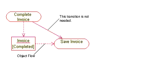
You do not need a transition if your diagram has two activities connected through an object and two corresponding object flows. The sample in Figure 51 does not require a transition because the transition is redundant.
Figure 51 Object Flow Sample
Understanding Objects and Object Flows
The object flow sample demonstrates how activities affect object state on activity diagrams. The object flow sample illustrates three important aspects of activity diagram objects:
- Objects may appear more than once and in several states.
- Activities may change object states.
- Objects connect with activities through object flows.
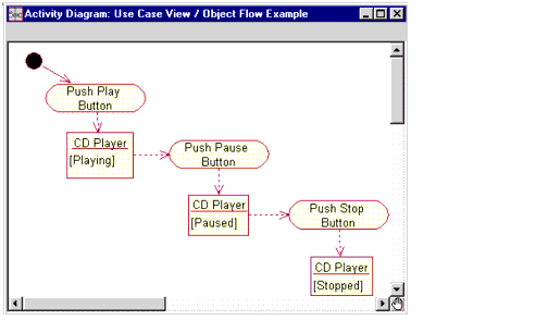
Figure 52 CD Player Sample
In Figure 52 , notice that the CD Player object appears on the diagram more than once. However, each object appears in a different state: playing, paused, and stopped. Each activity in the sample changes the state of the CD Player when you push the various buttons or perform the activity. For example, when you push the Pause button, the state of the CD Player changes to [Paused].
In most cases, the same object may be (and usually is) the output of one activity and the input of one or more subsequent activities.
Changing the State of an Object
To change the state of an object on an activity diagram:
- 1 Double-click the object to display the Object Specification.
- 2 Select New from the State list.
- 3 Enter descriptive information about the object state in the State Specification.
- 4 Click OK to close the State Specification.
- 5 Click OK to close the Object Specification.
Shared State Machine Diagram Model ElementsThis section describes the elements that can appear in both activity diagrams and statechart diagrams:
States
A state represents a condition or situation in the life of an object during which it satisfies some condition or waits for some event. Each state represents the cumulative history of its behavior.
Start and End States
A start state explicitly shows the beginning of a workflow on an activity diagram or the beginning of the events that cause a transition on a statechart. You can have only one start state on a statechart or activity diagram.
An end state represents a final or terminal state on an activity diagram or statechart diagram. Place an end state when you want to explicitly show the end of a workflow on an activity diagram or the end of a statechart diagram.
Transitions
A state transition indicates that an object in the source state will perform certain specified actions and enter the destination state when a specified event occurs or when certain conditions are satisfied. A state transition is a relationship between two states or two activities, or between an activity and a state.
You can show one or more state transitions from a state as long as each transition is unique. Transitions originating from a state cannot have the same event, unless there are conditions on the event. Transitions appear on statechart and activity diagrams.
You should label each state transition with the name of at least one event that causes the state transition. You do not have to use unique labels for state transitions because the same event can cause a transition to many different states or activities.
Transitions are labeled with the following syntax:
Only one event is allowed per transition, and one action per event.
Events, conditions, and actions must be added by editing the label or through the State Transition Specification.
Transition to Self
A transition to self is very similar to a state transition; however, it does not move the focus of control to another state or activity when an event occurs. A transition to self contains the same source and target state or activity.
A transition to self contains actions and events just like transitions.
The icon for a transition to self is a looped line with an arrowhead pointing toward the same source state or activity. The transition to self arc appears on the top of an activity or state icon.
Decisions
A decision represents a specific location on an activity diagram or statechart diagram where the workflow may branch based upon guard conditions. There may be more than two outgoing transitions with different guard conditions but, for the most part, a decision will have only two outgoing transitions determined by a Boolean expression.
Synchronizations
Synchronizations allow you to see a simultaneous workflow in an activity diagram or statechart diagram. They also visually define forks and joins representing parallel workflow.
Swimlane SpecificationA Swimlane Specification allows you to display and modify the properties and relationships of a swimlane on an activity diagram.
To display a Swimlane Specification, select the swimlane header on an activity diagram and double-click. You may also double-click on the swimlane icon in the browser.
Specification Content
The Swimlane Specification consists of the General tab.
Swimlane Specification--General Tab
Figure 53 Swimlane Specification--General Tab
Refer to the descriptions in the Introduction to Specifications chapter for information on the specification elements.
State and Activity SpecificationA State and Activity Specification allows you to display and modify the properties and relationships of a state or activity on a statechart diagram or activity diagram. Although a state and activity have almost identical features, they are used for different purposes. Start states and end states use the same specifications as states because they are a type of state. However, they appear as circles on statechart and activity diagrams.
Specification Content
The State, Activity, Start State, and End State Specifications consists of the following tabs: General, Action, Transitions, and Swimlanes.
State and Activity Specification--General Tab
Figure 54 State and Activity Specification--General Tab
Refer to the descriptions in the Introduction to Specifications chapter for information on the specification elements not covered in the following section.
Information about the name, stereotype, owner, context, documentation, state/activity history, and sub state/activity history is entered or displayed on the tab.
State/Activity History
History provides a mechanism to return to the most recently visited state when transitioning directly to a state with substates. History applies to the level in which it appears. It may also be applied to the lowest depth of nested states.
To apply history at the state or activity level, click State/activity history. Click Sub state/activity history to apply history to all the depths of nested states or activities within the state or activity level.
State and Activity Specification--Actions Tab
Figure 55 State and Activity Specification--Actions Tab
Information about the type and action expression is entered or displayed on this tab.
Type
The Type field identifier bar lists the kind of action specified in the Action Specification.
Action Expression
The Action Expression field identifier bar lists the four possible timing options that specify when to carry out an action, and it specifies the types of actions that are carried out. You can modify the action settings through the Action Specification Detail tab.
For information on the Action Specification, refer to the Action Specification.
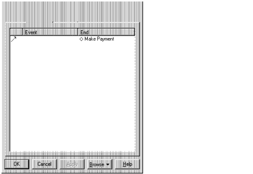
State and Activity Specification--Transitions Tab
Figure 56 State and Activity Specification--Transitions Tab
Information about the icon, event, and end is displayed on this tab.
State and Activity Specification--Swimlanes Tab
Figure 57 State and Activity Specification--Swimlanes Tab
Information about the swimlane name is displayed on this tab.
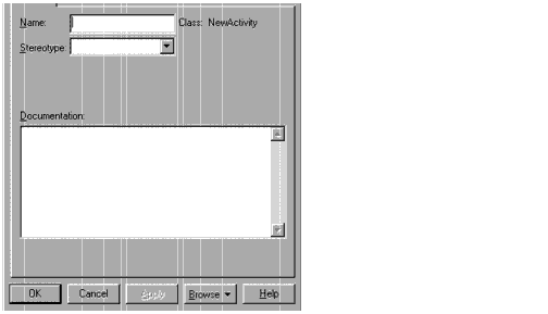
Action SpecificationAn Action Specification allows you to display and modify the action properties in a statechart diagram or activity diagram.
To define a new action on a state or activity:
- 1 Click the Actions tab of a State Specification or Activity Specification.
- 2 Right-click to display the shortcut menu.
- 3 Click Insert and an entry item is added.
- 4 Double-click the entry to display the Action Specification.
- 5 Type the action description in the Name field. If this field is not active, click Action on the Type field.
If you select Send Event, you may type optional arguments to the triggered event in the Send Arguments field and the name of another object in the model in the Send Target field.
State and Activity Actions
Each state and activity on a statechart or activity diagram may contain any number of internal actions. An action is best described as a "task" that takes place while inside a state or activity. There are four possible actions within a state or activity:
- On Entry
- On Exit
- Do
- On Event
On Event
The On Event parameters are only enabled when you set the On Event timing parameter.
Event--In a statechart or activity diagram, an event is an occurrence that can trigger a state transition. Type the name of the event that will trigger the action.
Arguments--Consist of any optional arguments associated with the event.
Condition--May contain a conditional Boolean expression.
There is an advantage to using an On Event state action rather than a transition to self. Transitions to self trigger all the actions associated with a state; whereas, state actions handle internal state transitions. This provides you with the control to process an internal event without triggering the entry and exit actions. The Trigger Specification contains the same features as the Action Specification. The Trigger Specification defines the properties of a trigger.
Specification Content
The Action Specification consists of the Detail tab.
State Transition SpecificationA State Transition Specification allows you to display and modify the properties and relationships of a transition on a statechart diagram or activity diagram. The State Transition Specification lists the events and actions that are comprised by the transition.
Specification Contents
The State Transition Specification consists of the following tabs: General and Detail.
State Transition Specification--General Tab
Figure 58 State Transition Specification--General Tab
Refer to the descriptions earlier in this chapter or in the Introduction to Specifications chapter for information on the specification elements.
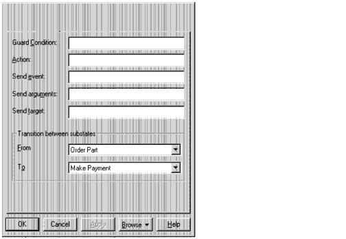
Transition Specification--Detail Tab
Figure 59 State Transition Specification--Detail Tab
Guard Condition
Conditional state transitions are triggered only when the conditional expression evaluates to true. Conditions are denoted by surrounding brackets:
To add a condition, click Guard Condition on the State Transition Specification and type the conditional expression. You may also include a condition by selecting the event label and changing the text.
Transition Between Substates
Transition between substates is useful when a transition is placed to or from a substate that has been hidden from view. The From field displays the state name from which the transition is initiated. The To field displays the state name to which the transition is pointing. Both fields are active at all times.
To enter a transition substate, click the scrolling arrow on the right side of the field. A list of potential transition substates will be presented. The list includes the name of all the states that reside within the bounds of the top level superstate, including the superstate. Select a state from the list.
Decision SpecificationA Decision Specification allows you to display and modify the properties and relationships of a decision on a statechart diagram or activity diagram.
The Decision Specification consists of the following tabs: General, Transitions, and Swimlanes.
Decision Specification--General Tab
Figure 60 Decision Specification--General Tab
Refer to the descriptions earlier in this chapter or in the Introduction to Specifications chapter for information on the specification elements.
Decision Specification--Transitions Tab
Figure 61 Decision Specification--Transitions Tab
Refer to the descriptions in the Introduction to Specifications chapter for information on the specification elements.
Decision Specification--Swimlanes Tab
Figure 62 Decision Specification--Swimlanes Tab
Refer to the descriptions in the Introduction to Specifications chapter for information on the specification elements.
Synchronization SpecificationA Synchronization Specification allows you to display and modify the properties and relationships of a synchronization on a statechart diagram or activity diagram.
The Synchronization Specification consists of the following tabs: General and Transitions.
Synchronization Specification--General Tab
Figure 63 Synchronization Specification--General Tab
Refer to the descriptions earlier in this chapter or in the Introduction to Specifications chapter for information on the specification elements.
Synchronization Specification--Transitions Tab
Figure 64 Synchronization Specification--Transitions Tab
Refer to the descriptions in the Introduction to Specifications chapter for information on the specification elements.
Object Specification (Activity Diagrams)An Object Specification allows you to display and modify the properties of an activity diagram object. The object specifications that appear from objects on an activity diagram are slightly different from the object specifications derived from a sequence or collaboration diagram. Activity diagram object specifications contain state and stereotype menus.
The Object Specification for an activity diagram consists of the following tabs: General, Incoming Object Flows, and Outgoing Object Flows.
Object Specification--General Tab
Figure 65 Object Specification--General Tab
Refer to the descriptions in the Introduction to Specifications chapter for information on the specification elements not covered in the following section.
State
The State drop-down list specifies and displays the object state.
Object Specification--Incoming Object Flows Tab
Figure 66 Object Specification--Incoming Object Flows Tab
The Incoming Object Flows tab displays the name of all incoming object flows.
Object Specification--Outgoing Object Flows Tab
Figure 67 Object Specification--Outgoing Object Flows Tab
The Outgoing Object Flows tab displays the name of all outgoing object flows.
Object Flow SpecificationAn Object Flow Specification allows you to display and modify the properties and relationships of an object flow on an activity diagram.
The Object Flow Specification consists of the General tab.
Object Flow Specification--General Tab
Figure 68 Object Flow Specification--General Tab
Refer to the descriptions in the Introduction to Specifications chapter for information on the specification elements.
| Rational Software Corporation
http://www.rational.com support@rational.com techpubs@rational.com Copyright © 1993-2001, Rational Software Corporation. All rights reserved. |