Introduction to Diagrams
ContentsThis chapter is organized as follows:
- Overview
- Diagram Windows
- Creating, Linking, Displaying, Renaming, and Deleting Diagrams
- Creating and Naming Model Elements
- Manipulating Icons
- Deleting Model Elements
- Correlations
- Laying Out a Diagram
- Adorning the Diagrams
- Understanding Model Workspaces
OverviewDiagrams are views of the information contained in a model. Rational Rose automatically maintains consistency between the diagram and its specifications. You can change properties or relationships by editing the specification or modifying the icon on the diagram. The associated diagrams or specifications are automatically updated.
Diagram WindowsIn a diagram window, you can create and modify graphical views of the model. Rational Rose supports the following kinds of diagrams:
- Class diagram
- Use-case diagram
- Collaboration diagram
- Sequence diagram
- Component diagram
- Statechart diagram
- Deployment diagram
- Activity diagram
Each icon on a diagram represents an element in the model. Since diagrams illustrate multiple views of a model, each model element can appear in none, one, or several of a model's diagrams. You can control which elements and properties appear on each diagram.
To add icons to a diagram, click Tools > Create and click one of the model elements. Click the diagram to place the element.
Viewing Diagrams
When a diagram is opened, it is displayed in a window within the application window. This diagram window has its own control-menu box, title bar, minimize button, and maximize button. Each diagram window also has vertical and horizontal scroll bars for panning across diagrams larger than the window. The application window presents a toolbox that contains tools appropriate for the current diagram.
Figure 6 Diagram Window
You can resize a diagram window by using the left mouse button to drag a side or corner of the diagram's border. You can reduce a diagram to an icon by clicking its minimize button.
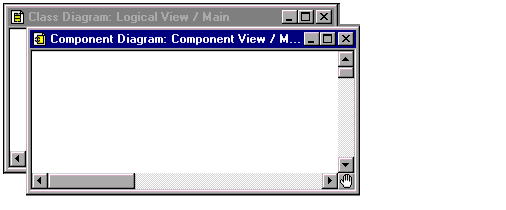
Displaying Multiple Diagrams
You can display multiple diagrams simultaneously in the application window. To display diagrams in cascaded windows (Figure 7) or tiled windows (Figure 8), click Window > Cascade or Tile.
Figure 7 Multiple Diagrams--Cascade Windows
Figure 8 Multiple Diagrams--Tiled Windows
The shaded title bar indicates that it is the current diagram. Diagram-specific commands apply to the current diagram, and the application window displays the toolbox associated with the current diagram. Menu commands and toolbox icons not appropriate for the current diagram are dimmed and cannot be used. You can make a diagram "current" by clicking it.
Creating, Linking, Displaying, Renaming, and Deleting DiagramsCreating a New Diagram
- 1 Click Browse > xxx Diagram, where xxx is the diagram type. (If you select Deployment Diagram, the diagram is immediately displayed and the following steps can be ignored.)
- 2 In the resulting dialog box, select a view from the list on the left.
- 3 Click <New> from the list on the right. (If you are creating a new interaction diagram, you must click either Sequence or Collaboration from the New Interaction dialog box.)
- 4 Click OK.
- 5 Type the diagram title. If you do not enter a title, the diagram is labeled untitled.
- 6 Click OK.
Linking a Diagram
You can link one diagram to another diagram through the note icon. This feature works somewhat like the shortcut method you may be familiar with in the Windows operating environment. Once the diagram is linked, you can double-click the note and the linked diagram is immediately displayed. A linked diagram is indicated by underlined text in the note.
- 1 Create a note on any diagram.
- 2 Display the browser if not already visible.
- 3 In the browser, locate the diagram that you want to link.
- 4 Drag the diagram icon from the browser onto the note icon on the diagram.
As you position the cursor onto the note, you will see the shortcut symbol (a dotted square and a curved arrow inside a solid square). Also, the fully qualified name is displayed in an underline font.
Note: You may need to resize the note to see the entire name.
- 5 Change the text in the note (if desired) to something more meaningful to your project.
- 6 Double-click the note to view the linked diagram.
Displaying a Diagram
- 1 Click Browse > xxx Diagram, where xxx is the diagram type. (If you select Deployment Diagram the diagram is immediately displayed and the following steps can be ignored.)
- 2 In the resulting dialog box, select an element from the list on the left.
- 3 Select a diagram from the list on the right.
- 4 Click OK.
Renaming a Diagram
Note: You cannot rename a deployment diagram.
- 1 Click Browse > xxx Diagram, where xxx is the diagram type.
- 2 In the resulting dialog box, select the package containing the diagram from the list on the left.
- 3 Select the diagram from the list on the right.
- 4 Click Rename.
- 5 Type a new diagram title.
- 6 Click OK.
Deleting a Diagram
- 1 Click Browse > xxx Diagram, where xxx is the diagram type.
- 2 In the resulting dialog box, select the package containing the diagram from the list on the left.
- 3 Select the diagram from the list on the right.
- 4 Click Delete.
- 5 Click Yes on the confirmation box.
Creating and Naming Model ElementsCreating an Element on the Diagram
- 1 Click the appropriate creation tool.
- 2 Click a location in the diagram.
Creating an Element in the Browser
- 1 Click the appropriate package.
- 2 From the shortcut menu, click New, and then point to the element you want to create.
Naming Model Elements
You can name model elements with any combination of characters that are meaningful to you. Depending on the model element and its location, you may or may not be restricted to unique names.
For example, actors, use cases, classes, components, and packages that reside in different packages do not require unique names. When different elements have the same name, the elements are said to be "overloaded."
Overloading gives you the flexibility of using existing software libraries that may have the exact names you have in your code or in another software library.
Overloading also allows you to do multi-lingual, component-based development. For example, an application can be modeled even if the GUI for screen input is in VB or Java, the processing is in C++, and the database in Oracle. In this example, each application can have its definition of a class "Customer" do different things.
Another useful feature of overloading is the ability to have actors in the use-case view and classes in the logical view with the same name.
When naming an element, it is important to note that in some cases an overloaded element is created, while in other cases, the existing element with the same name is used (and therefore an overloaded element is not created).
To name an element on the diagram:
- 1 Create a new element on the diagram from the toolbox.
- 2 Type in a name. As soon as you start typing, a pop-up box listing all the available class names in the model is displayed.
You can select one of the highlighted names by double-clicking a name or by pressing the enter or tab key. Otherwise, you can continue typing (and click outside the edit area) to enter a new name.
- If you do not want to see this window, you can turn this option off. To do so, click Tools > Options. Click the Diagram tab. Under the Miscellaneous section on the lower left, click Class Name Completion to turn the feature off.
To create/name an overloaded element on the diagram:
If you want to create an overloaded element name on the diagram, you must enter the name through the specification. If you instead enter the duplicate name on the element in the diagram, you will be using an existing element rather than creating a new one with its own characteristics.
- 1 Create a new element on the diagram from the toolbox.
- 2 Double-click the element or click Browse > Specification, to display the specification.
- 3 Type a name in the name field.
- 4 Click OK.
If this name already exists in another package, a warning dialog is displayed telling you the name of the element and type already exists in another package. For example: "Class AA now exists in multiple name spaces."
You can dismiss this box either by clicking Cancel which ignores the name or OK. If you do not want to see the dialog box anymore, select the Don't warn anymore this session check box. To start seeing the dialog box again, restart the application.
The element is now named with a duplicate name, but has its own unique characteristics.
To place an overloaded element on the diagram from the browser:
From the browser, drag the element onto the diagram.
If the element belongs to a parent different from the diagram, and Show Visibility is on, the element is annotated with the term `(from x)' where x is the element's location. If Show Visibility is off, only the element name is displayed.
A fully qualified name is displayed as you place your pointer over the model element. A fully qualified name consists of the element hierachy (starting at the package level), where each level is separated by double colons. For example, Logical View::Package B::Class 1 is a fully qualified name.
- 1 Click the name of an icon to display the insertion point (flashing vertical bar).
- 2 Backspace and type additional text.
Note: Stereotypes in the form <<stereotype>> are extracted from the name of an item when you edit it.
- 3 Click outside the named icon.
Alternatively, you can double-click an icon to display its specification; modify the Name field, and click OK.
If double-clicking a logical package icon displays the main class diagram, click Tools > Options, and then click the Diagram tab. Clear the Double-Click to Diagram check box. With this option turned off, double-clicking a package will display the specification.
Reassigning Model Elements
This feature allows you to make a selected icon represent a different model element.
- 1 Select the icon to reassign.
- 2 Click Edit > Reassign.
The dialog box lists the packages in the model on the left and a list of the valid elements to choose from on the right.
- 3 Choose the model element that the selected icon will represent.
Manipulating IconsManipulating icons includes selecting, deselecting, moving, and resizing. These features are similar to those you might find in most major drawing tools.
Selecting Icons
- Left-click the icon to be selected.
- 1 Point near the border of one of the icons to be selected.
- 2 Left-drag to create a dashed selection box around the icons you want to select.
- 3 Release the left mouse button.
Rational Rose displays each icon's selection handles, and deselects all other icons. Figure 9 shows multiple elements selected in a diagram:
Figure 9 Selected Elements in a Diagram
Note: You can select any element in the diagram.
Deselecting Icons
- Click any open area of the diagram.
- 1 Press and hold the control or shift key.
- 2 Click the icon.
Resizing an Icon
- 1 Click the icon to be resized.
- 2 Choose the appropriate selection handle and left-drag to the new dimension.
Moving One or More Icons
To move icons using the mouse:
- 1 Select the icon(s).
- 2 Left-drag to the desired location.
- 3 Release the left mouse button.
To move icons using the keyboard:
- 1 Select the icon(s).
- 2 Use the four directional arrow keys to move the icons by one pixel in the indicated direction, or press the ctrl key while using the arrow keys to move eight pixels in the indicated direction.
If the snap-to-grid operation is enabled, icons and text boxes that are created or moved will be aligned with the nearest grid coordinate. To enable or disable this operation, in the Options dialog box, click Snap To Grid. To specify the size of the grid in pixels, on the Options dialog box, click Grid Size.
Changing from One Kind of Element or Relationship to Another
- 1 Click the toolbox tool bearing the desired icon.
- 2 Press and hold the ALT or META key.
- 3 Click the icon to be changed.
Cutting, Copying, and Pasting Icons
You can cut, copy, and paste icons between different diagram windows using commands on the Edit menu or the tools on the toolbar.
Clicking Edit > Cut, Copy, or Paste can manipulate selections containing icons and text in diagrams, and text information in specification fields. Clicking Edit > Cut performs a delete operation on some diagrams and a delete from model operation on others.
Clicking Copy will copy the selected icons to the platform Clipboard. Clicking Cut performs this same operation and then performs a delete operation. You can use these commands to move portions or all of a class diagram to other tools that support the platform Clipboard.
Clicking Paste in a class diagram adds icons from the Clipboard to the center of the current diagram as if you manually created them with the toolbox.
Clicking Edit > Undo reverses the last Delete, Delete From Model, or Cut.
The Edit menu also provides commands that allow you to Select All, Find, and Rename icons.
The Browse menu provides commands to navigate among diagrams, and create, rename, and delete them.
When you right-click an icon, Rational Rose displays a shortcut menu. This menu allows you to modify properties (for icons that represent relationships) or select properties to be displayed within the icon.
Deleting Model ElementsThere are two ways to delete model elements in Rational Rose: you can perform a shallow delete or a deep delete. A shallow delete removes the element icon from a diagram. A deep delete removes model elements from a model completely.
Shallow Delete
A shallow delete is useful when you want to remove a model element icon from a diagram but keep the model element in the model. A shallow delete keeps the model element in the browser and removes the icon of the element from the diagram.
To perform a shallow delete on a selected model element that appears on a diagram:
- Click Edit > Delete.
- Press DELETE.
Note: If you perform a shallow delete on an element without a name, Rational Rose will delete the model element completely from the model.
Deep Delete
A deep delete is useful when you want to remove a model element completely from a model.
To perform a deep delete on a selected diagram model element(s):
- Click Edit > Delete from Model.
- Press CTRL + D.
- Right-click an element in the browser and then click Delete from the shortcut menu.
CorrelationsDepending on the diagram selected, a correlation can be a relationship, a link, a dependency, a transition, or a connection. The word correlation can stand for any of the items previously listed.
Creating Correlations Between Elements
- 1 Click the relationship's tool in the toolbox.
- 2 Point to the client icon on the diagram.
- 3 Press and hold the left mouse button.
- 4 Drag the pointer to the supplier icon on the diagram.
- You can create vertices by releasing the mouse button while still on the diagram. A new vertex is created each time you lift the mouse button.
- You can modify a vertex by dragging on a selected vertex.
- Joining an inherits relationship to another inherits relationship will create a tree, rather than a hierarchical structure.
- 5 Release the mouse button at the supplier element.
Bending a Correlation Icon
- 1 Point to the section of the icon to introduce or modify a bend.
- 2 Left-drag the pointer to the new location for that section of the icon.
- 3 Release the mouse button.
When you release the mouse button, Rational Rose redraws the correlation icon with the new or modified bend. If the modification nearly eliminates a bend, Rational Rose will replace the bend with a straight segment.
Reconnecting a Correlation Icon from One Icon to Another
- 1 Point to the end you want to reconnect.
- 2 Left-drag to the new icon.
- 3 Release the left mouse button.
Rational Rose redraws the relationship between the two icons and updates the model to reflect the change, or reports an error if the change is not legal.
Naming a Correlation
To name a newly-created correlation:
- 1 Click the icon.
- 2 Type the name.
- 3 Click outside the named icon.
To change the name of a correlation:
- 1 Click the name to display a flashing vertical bar that designates the insertion point.
- 2 Backspace and type additional text.
- 3 Click outside the named icon.
Alternatively, you can change the name in the Name field of the specification.
Laying Out a DiagramWhen a diagram contains many elements (also called shapes) and many relationships (also called correlations), it can become difficult to read. The layout diagram feature is designed to make a diagram easier to read by rearranging elements on a diagram to clarify their relationships. This is done by minimizing the number of crossed links and positioning shapes in an order that reflects their relationships.
Figure 10 provides an example of how the Layout Diagram command rearranges classes in a class diagram. Additional information and examples about the feature can be found in the "Layout Diagram (Overview)" topic in the online Help.
Figure 10 Example Layout of a Class Diagram
When you perform a layout command, Rational Rose follows these two rules:
- Shapes that have relationships with other shapes are rearranged based on their relationship(s) in the diagram. Refer to the Layout Diagram (Overview) topic in the online Help for more information.
- Shapes that do not have relationships (called "unconnected shapes") are placed in one or more rows at the bottom of the diagram or selected area. Examples of unconnected shapes include any element (e.g., class, actor, package) that does not have a relationship to another element, notes that are not attached to elements, and text boxes created with the ABC Text tool.
Laying Out All Shapes in a Diagram
- 1 Click Tools > Options to display the Options dialog box.
- 2 On the General tab, set the options under Layout Options. For help on an option, click the question mark
, and then click the option.
- 3 Click OK to save the settings and close the dialog box.
- 4 Click Format > Layout Diagram.
Rational Rose rearranges all shapes in the diagram according to the settings specified in the Options dialog box.
Note: To undo the layout, select Edit > Undo.
Laying Out Selected Shapes in a Diagram
- 1 Select the shapes and relationships in the diagram that you want to rearrange.
Shapes will be rearranged either in an order based on their relationships if the relationships between them are selected or in horizontal rows if only the shapes are selected. If you are working in an activity diagram or a three-tier diagram, all shapes that you select must be within the same swimlane.
- 2 Click Format > Layout Selected Shapes.
Rational Rose rearranges the selected shapes within the area of the diagram that they currently occupy.
Note: To undo the layout, select Edit > Undo.
Adorning the DiagramsYou can select which adornments (symbols) to display on the diagram through the shortcut menu. The shortcut menu is displayed by right-clicking an icon. You can click the menu choices to enable and disable them; a check mark indicates that a choice is enabled. You can also adorn your diagram with annotations that you add. This annotation or adornment is typically a note to yourself or others about specification features or functions not noted by Rational Rose.
Placing Text in a Diagram
- 1 Choose the ABC tool from the toolbox.
- 2 Click a location in the diagram.
Manipulating Text
To change the default font parameters:
- 1 Ensure that nothing is selected by clicking an empty region in any diagram.
- 2 In the Options dialog box, click Font or Font Size. The default font parameters apply to all diagrams.
To change the dimensions of the invisible box containing text in a diagram:
- 1 Click the text to make the text box's selection handles visible.
- 2 Left-drag the appropriate selection handle to resize the text box.
To move the invisible box containing text in a diagram using the mouse:
- 1 Click the text.
- 2 Left-drag the text to the location.
- 3 Release the left mouse button.
To move the invisible box containing text in a diagram using the keyboard:
- 1 Click the text.
- 2 Use the four arrow keys to move the text box by one pixel in the indicated direction, or press the ctrl key while using the arrow keys to move eight pixels in the desired direction.
Understanding Model WorkspacesA model workspace is a snapshot of all currently loaded units and open diagrams. By defining one or more workspaces, you can set up your working environment in Rational Rose and return to that environment each time you are ready to work. When you load the workspace, Rose restores the snapshot by loading the specified controlled units and opening the correct diagrams.
If you are working with large models that are divided into many controlled units, you will notice even greater productivity gains by using workspaces to load predefined units and diagrams.
Differences Between a Saved Model and a Model Workspace
A saved Rational Rose model contains the diagrams, elements, and controlled units that make up the complete model. A model workspace contains the actual state of open diagrams and controlled units for a specific saved model at a given point in time.
It is possible to have multiple workspaces corresponding to only one model. For example, during analysis and design, you might want to define one model workspace that displays the most important analysis diagrams and controlled units, and another model workspace that displays the most important design diagrams and controlled units. Each workspace is different but points to the same model.
It is also important to note that saving a model workspace will not affect how the model is loaded on another machine. If a co-worker wants to load a model using a model workspace you defined on your machine, the co-worker must have a copy of the model workspace and model located in the same folder on his or her machine.
By default, Rational Rose will name the workspace <model name>-<Operating System User Name>.wsp. For example, the name of a saved model workspace might look like MyModelName-JillUser.wsp.
Note: Rational Rose stores all workspace files (*.wsp) in the workspaces folder.
Model Workspace Scenario
The following scenario shows how using model workspaces can benefit a team working on a large model. A new software developer has just joined a distributed team that is working on a very large model containing over 200 controlled units. Through the course of the next several months, the new developer will model several systems in the use case model and will modify the business actors and use cases (as shown in Figure 11). In order to help the new developer, the team's project manager created a model workspace that will load all of the units the software developer will be responsible for, as well as some of the more important diagrams.
When the developer loads the model workspace, the Business Actors, Business Use Cases, eCommerce System, POS System, Telesales System, and Warehouse System controlled units all load. (See Figure 11.) The workspace configuration will also display some important class and activity diagrams in the diagram window.
Figure 11 Model Workspace Loaded Units
The model workspace will help the new developer by:
- Automatically loading the controlled units for which the developer is responsible
- Displaying some of the more important diagrams the developer should examine first
- Saving the developer time because Rational Rose only has to load six out of 200+ controlled units
- Eliminating confusion by limiting the scope of information the developer sees
After working in the model, the developer can easily customize the model workspace the project manager created, or create additional model workspaces for greater efficiency.
Saving a Model Workspace
- 1 Click File > Save Model Workspace.
- 2 Name your workspace file in the Save As dialog box. By default, Rational Rose will name the workspace <model name>-<Operating System User Name>.wsp. For example, the name of a saved model workspace might look like MyModelName-JillUser.wsp.
Note: Rational Rose stores all workspace files (*.wsp) in the workspaces folder.
Loading a Model Workspace
- 1 Click File > Load Model Workspace.
- 2 Select the name of workspace file (*.wsp) to load.
- 3 Click Open.
| Rational Software Corporation
http://www.rational.com support@rational.com techpubs@rational.com Copyright © 1993-2001, Rational Software Corporation. All rights reserved. |